
Original resources · Version 1.0
Automotive Engineering Diagrams and Data
Three sourced reference packs for vehicle development, driving automation and in-vehicle networks. Download, analyse, teach or cite them.
What is in the EV-Global automotive engineering reference library? It contains original diagrams and CSV datasets that turn three dense vehicle-engineering subjects into reusable references: automotive development from concept to SOP, SAE driving-automation responsibility from L0 to L5, and CAN, LIN plus Automotive Ethernet in a zonal architecture. Every pack states its sources, version and limitations.
These are editorial syntheses, not copied standards charts. The diagrams are designed for quick explanation. The CSV files expose the same logic for analysis, teaching and fact checking.
Reference 01
Automotive development process: concept to SOP
The map separates product design, manufacturing-process design, validation, PPAP, SOP and ramp-up. It also shows the point most summaries miss: APQP spans the evidence-building work, while PPAP is a customer approval process and SOP is a programme milestone. Exact gates, submission levels and timing vary by OEM and customer.
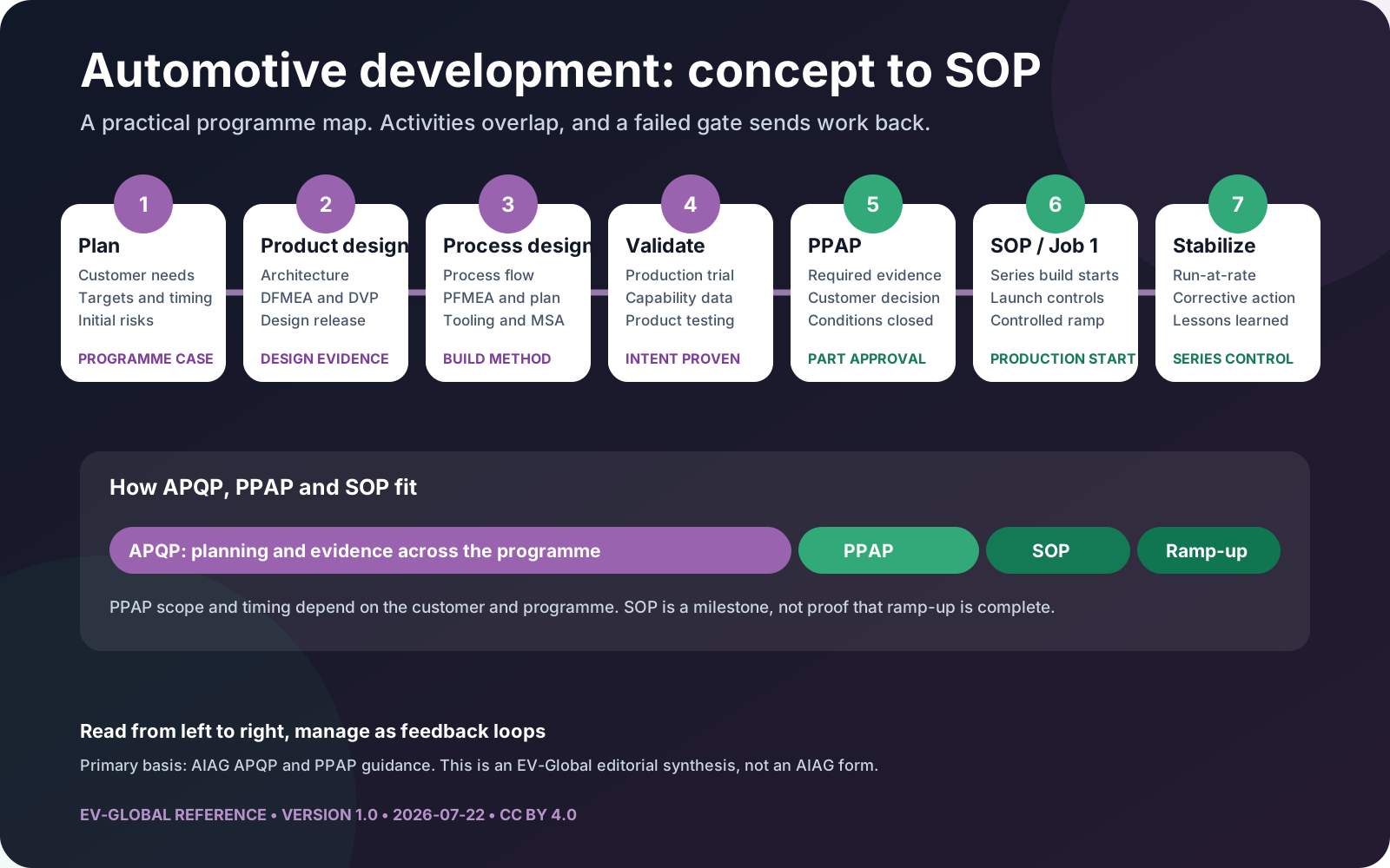
Use it with our full guides to the automotive product development process, APQP and PPAP and Start of Production.
Primary basis: AIAG's official APQP overview and Core Tools relationship. The map is an EV-Global synthesis, not an AIAG form or substitute for customer-specific requirements.
Reference 02
SAE autonomous driving levels L0-L5
The matrix answers three questions for every level: who controls the vehicle, who monitors the road, and who performs fallback. This makes the L2 to L3 boundary visible without treating the levels as a simple ladder of hardware capability.
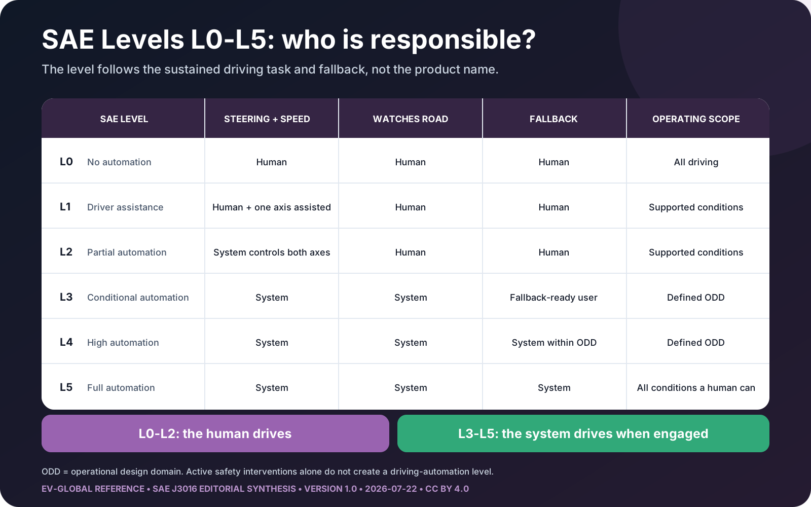
Continue with the detailed SAE automation levels explainer, our precise Level 2 vs Level 3 comparison and the Waymo Level 4 case study.
Primary basis: SAE J3016 and the NHTSA automation-level explanation. Example categories illustrate the taxonomy and do not certify a particular product.
Reference 03
CAN vs LIN vs Automotive Ethernet
The architecture diagram shows why the network debate has no single winner. Automotive Ethernet connects central compute and zones. CAN and CAN FD remain efficient for robust local control. LIN keeps simple actuators cheap. The companion data adds rates, access models, use cases and limits for six network variants.
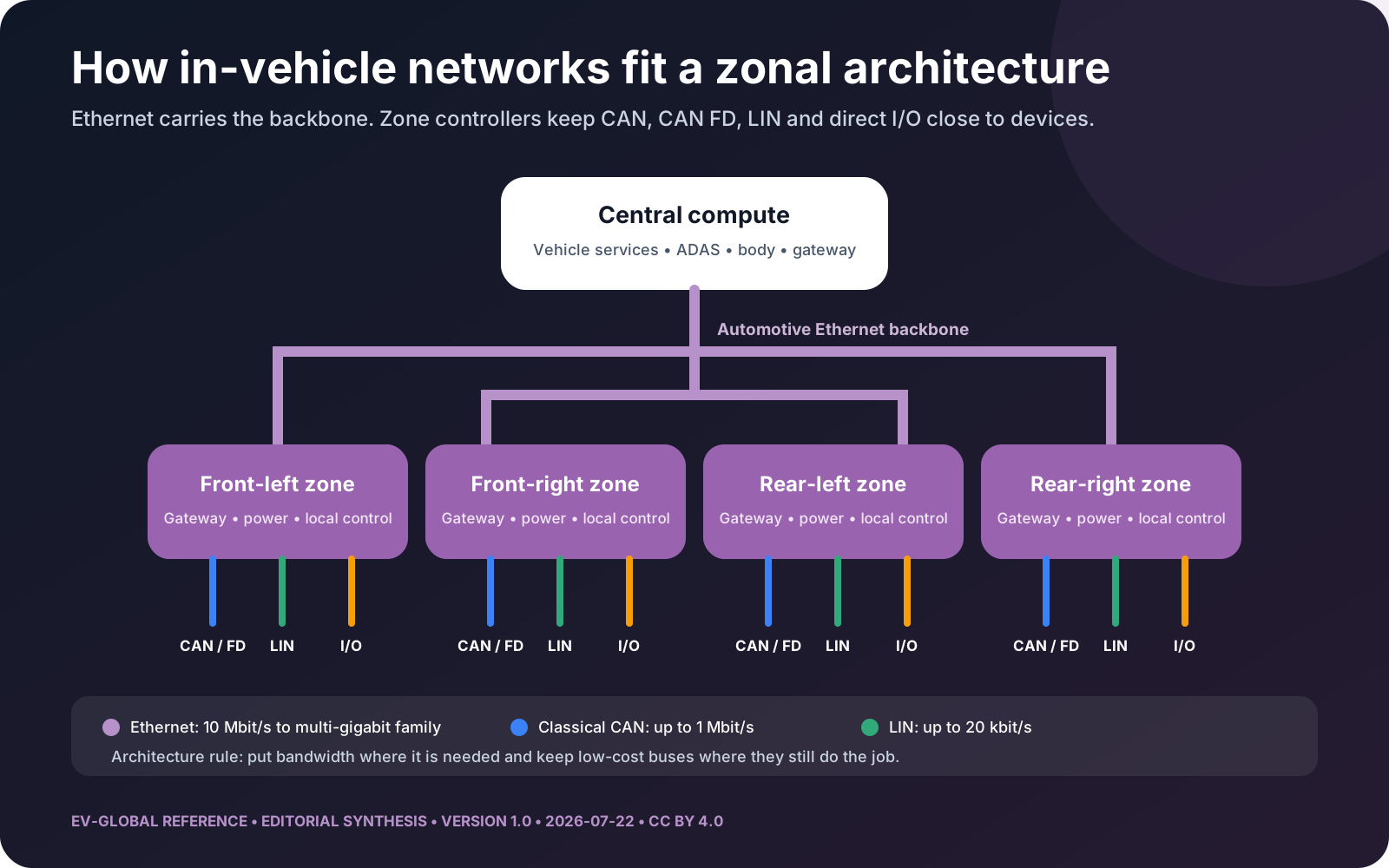
Read the technical detail in CAN vs LIN vs Automotive Ethernet, then connect it to domain and zonal E/E architecture and the software-defined vehicle stack.
Primary basis: the LIN 2.2A specification, Bosch's CAN and CAN FD data-rate overview, IEEE 802.3 single-pair Ethernet standards, OPEN Alliance and AUTOSAR architecture material.
Reuse and citation
Use the assets with attribution
The six diagrams and six datasets on this page are released under Creative Commons Attribution 4.0 International. You may share and adapt them, including commercially, if you credit EV-Global, link to this landing page and indicate whether you changed the material. Third-party standards and trademarks remain the property of their owners.
Suggested citation: EV-Global, “Automotive Engineering Reference Library,” version 1.0, 22 July 2026, https://ev-global.org/automotive-engineering/reference-library/.
Correction policy: send factual corrections through our contact page. Material changes receive a new version and updated date.